
Since the Project is very popular and I get a lot of inquiries , it is necessary here to clarify something.
The newest Firmware is on this side at the end as a link ! So please don’t ask me to send firmware! Thanks !
So please READ every LINE on this side !!!
- I’m NOT the Author of this project!!! For questions like eagle files or changing parts in the circuit, please ask DG7EAO !!!
- I does not selling parts or finish analyzers
- Software support no matter of course . This is a private project and I have a 12 hour job. If I like, I will answer your mails. But you can not count on it!!
- When the source code of you will be changed , or other hardware is used, I will never help you.
- I give no workshops in any programming language
- I’am not searching your bugs in your circuits. Be sure that the software is well testet, by over 50 OMs and ok. Use my firmware or leave it.
Sorry for that rules, but a lot of OM’s can’t read. Every RED rule have a reason with some mails. It must be easier to write a mail, as reading the project files ! I got over 50 mails, with questions, what can easy answered by this side and text file in the ZIP File.
So now we start….
I find in the internet a very interesting Project. He build with Arduino Modules a good Antenna Analyser.
Here you can download all information over the Basic original project:
http://dc2wk.schwab-intra.net/Arduino Analyser Schematics.rar
http://dc2wk.schwab-intra.net/Display Addon.rar
This is a project from DG7EAO. Thanks a lot to him!
The old page is deleted, I don’t know why. So I saved this schematics for us.
But I find a new page from Norbert: http://www.dg7eao.de/test/antennen-analysator/
To download my version of the firmware, see the link after the article.
I ordered the parts and start to build this little project.

For the modules I take IC-Sockets

The modules are installed

The finish analyzer
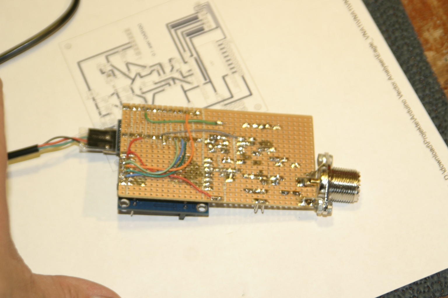
The underside

The test of the DDS Signal
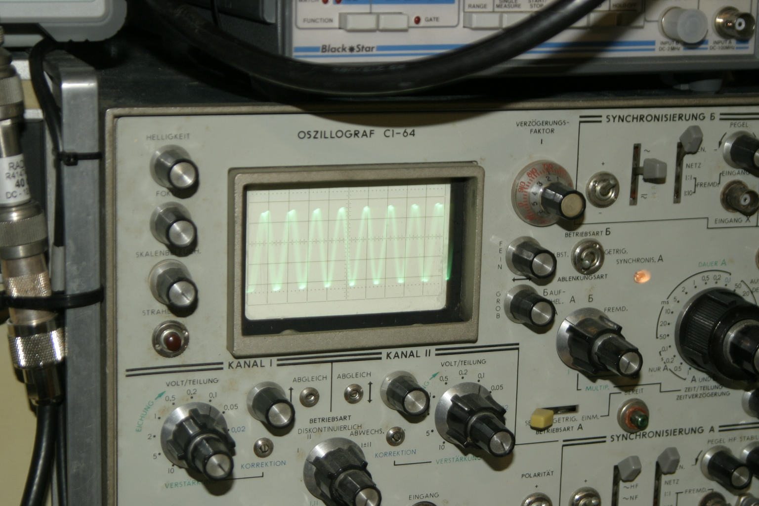
Works fine
Test measuring’s:

A Sirro CB Mobile Antenna

A DL7IO Hexbeam 10-20m

A Butternut HF5V Vertical 10-80m

You also can check a LC resonator
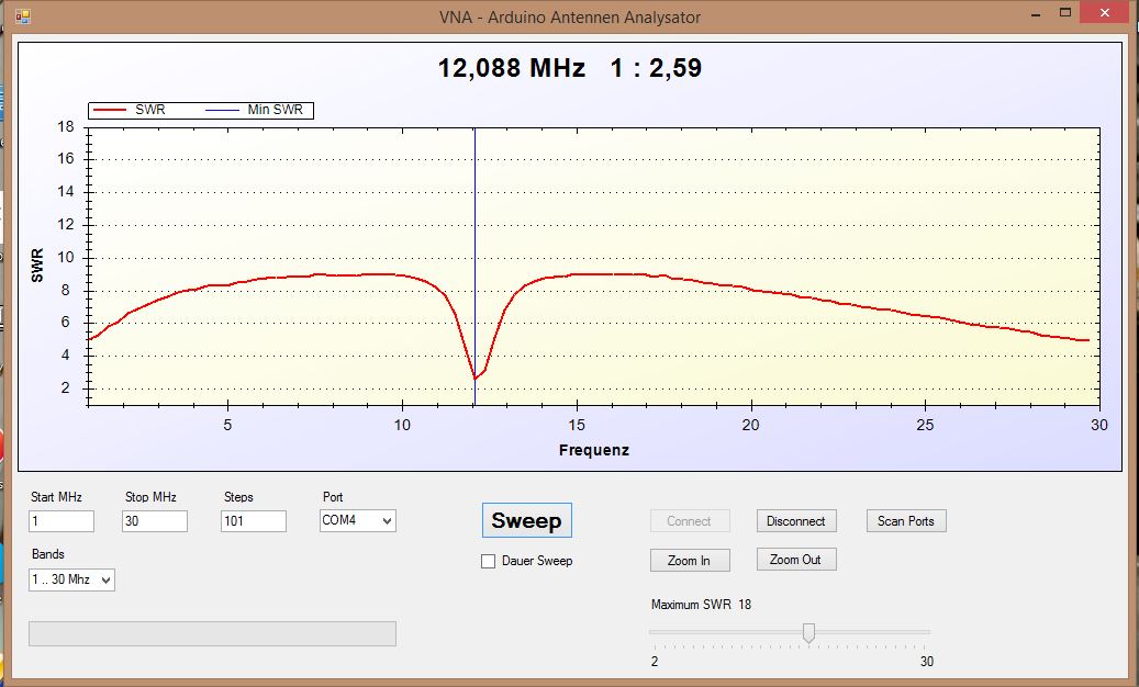
Here with a frequency from 12.088 MHz (0,9uH + 300pF)
The Costs of this project, without a case, was:
The Arduino Modules:
| 1x | USB auf RS232 TTL UART PL2303HX Converter Adapter Cable CP12005 F44 | 5,20 EUR | 5,20 EUR |
| 1x | Pro Mini Atmega328P Board Modul 5V/16MHz for Arduino-Compatible AR01011 J32 | 7,82 EUR | 7,82 EUR |
| 1x | AD9850 Module DDS Signal Generator 40Mhz CP13010 D54 | 10,99 EUR | 10,99 EUR |
Other Parts:
6x 100 Ohm 1%, RM 7,5 0,30 €
2x 10 K RM 7,5 0,06 €
2x 100 K RM 7,5 0,06 €
2x 4,99 K RM 7,5 0,10 €
2x 649 R RM 7,5 0,10 €
1x 1u RM 2.5 0,10 €
2x 100n RM 5 0,10 €
3x 10n RM 5 0,30 €
1x LM358 0,19 €
IC Sockets 0,50 €
2x Germanium Diode AA143 2,20 €
Cables 0,50 €
PL od BNC Jack 1,50€
circuit board 1,50 €
All together: 31,52 €
Update 1:

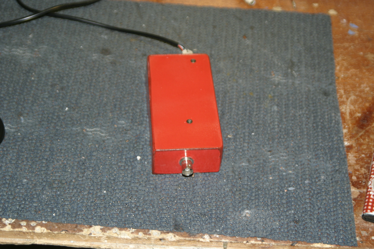
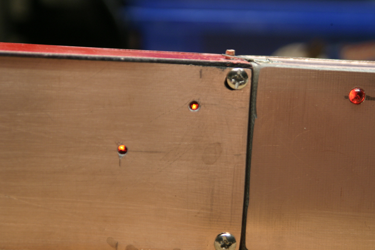
I build a case out of circuit board material

This is the front, place for the display later
The Cable on the left side is only connected if the analyzer is in Computer mode
As a stand alone analyzer there will be a battery case installed.
The underside. The case its 100% RF proof
With the RF Proof case, the measuring is near to that what I see with my transceiver.
Here the Butternut HF5V Vertical 10-80m, like some pictures before.
I also made a Battery Case with a 5V power supply and a 9V battery
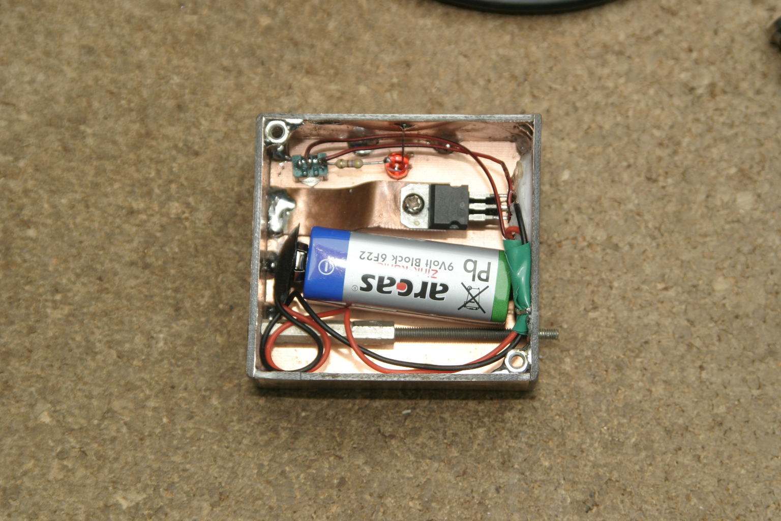
A 7805 and a electrolyte capacitor, that’s all

Special lock mechanism 🙂

Battery pack is plug in …
…and it works 🙂
Update 2:

My display is arrived 🙂 I test it first with my second arduino. If you build it on a test board like that, it will not be stable. For a short test it’s OK. The computer hangs often times. So keep your cable very short and work with shields!

The current is with the display together 61 mA. So my 9V battery is maybe to small.

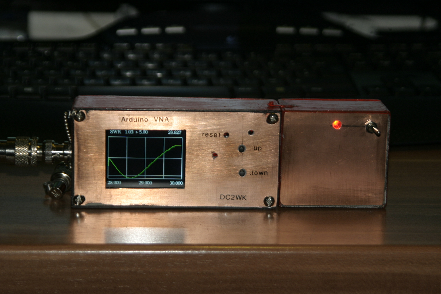
So I build it in. This is more stable as it looks

Display and switches in the case

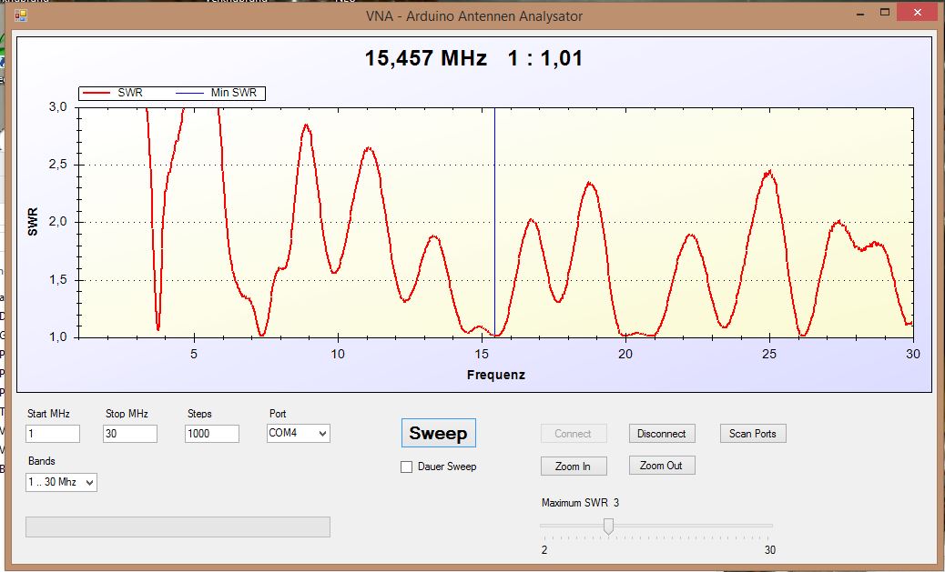
The Scan with my Butternut

The same Scan with the software over USB, this still works 🙂
In the following Pictures the Resolution in the Firmware was max. SWR = 5.
I change it later again to max. SWR = 10, that I can use it as a Dip-meter.

I modify the firmware so that I can switch over the complete band in details. Here 80m.
In the battery-pack I have now 2 accumulators with 3.6v and 1600mA together, so that I have over 7V. With the 7805 I make the 5V for the tester. I charge it with 9v. This is a 10m Mobile Antenna.
Update 3:

I add a third knob and a front plate. This third knob is connected to PIN4 and GND!
The Knobs are in my own firmware:
The first: 2 MHz up in a 3 MHz range (Detail sweep)
The second: 2 MHz down in a 3 MHz range (Detail sweep)
The third: Overview sweep from 1-30 MHz.
And I add a lost in % in the first line.
It’s very important that you are using exactly the same parts and modules!!!!!
A Firmware what is write for this Arduino and Display, will not work with a other!!!!!!!!!!!!! It only works with my three knob version!!!
Here you can download my own version of the firmware:
http://dc2wk.schwab-intra.net/DDS_sweeper1_TFT_swb.zip
And here my own version of the windows tool:
http://dc2wk.schwab-intra.net/VNA_Programm.zip
Videos:
Here the Resolution in the Firmware is max. SWR = 10.
I, interest at more details and software for Antenna Analyzer with display you update project
Zbig
Hi Zbig,
what you like to know?
Great Project!
Will you share the INO file and schematic?
73’s
Denis
KC6AUP
Hi Denis,
thanks for the nice comment. You will find all info’s (schematic, Info’s) in the first link on this project side.
The DC2WK Version of the firmware you can get from me per e-mail.
Erfolgreiches Design, einfache und schnelle Montage .Super. Ich habe Interesse an dem Programm und zeichnung.
Ich sende Ihnen das Programm via E-Mail.
Mit einer Zeichnung meinen Sie sicher den Schaltplan. Den finden sie oben in dem Beitrag.
https://lima05web.wordpress.com/2014/03/22/arduino-antennen-analysator-dg7eao/
Die Änderungen beschreibe ich dann in der Mail
Nette Grüße
Donald
Very interesting project.
Can you send me .ino files?
Best Regards
Sal
CT2IRJ
Hi Sal,
the files are on the way
73 de DC2WK
Hi,
I really like your project and are in the process of ordering my parts as needed.
Please if it’s no trouble could you also sent me your firmware.
Thank you
73 de ZS6PX
Hi ZS6PX,
no problem. I will try to send you the zip files.
73 de DC2WK
Donald
Hello, Donald.
I appreciate so much your project. I´d like to know if we can use the module AD9851 replacing the AD9850 instead. Thats because I need to work on the band till 65Mhz. In case it is possible, is there any suggestion in changing the circuitry to accept the AD9851? Still, do you have a project with Arduino that can meassure both the Impedance AND phase of the antenna?
Thanks in advance.
Hi Carlos,
thanks for the nice comment.
I think that you can use the AD9851 instead the AD9850, if all pins are the same.
The Firmware must can handle this, I think. The circuitry must can handle this too.
In the moment there too much work at my working place. So I have no time to try it out.
Let me know, if it does not working.
73 de DC2WK
Hi
Very good work.
Can you please send me the firmware?
73 de ZS1CF
hi, i would really like to get an email of your arduino code. It’s a great project
Hi, looks like this page lima05web.wordpress.com is no longer available.
since the authors have deleted this site.
Any chance to get a copy online somewhere else?
73
DL3NEW
Hi OM DL3NEW,
I find it unfortunate that the page has been deleted 🙁
It was a great page.
So I saved the schematics for us and add two links do download all Information.
Have a lot of fun
73 de DC2WK
Hey,
ein wirklich tolles Projekt. Ich hätte sehr großes Interesse an der Firmware. wäre es möglich, diese per Mail zu bekommen?
mni tnx es
vy 73 es 55 de Andi DC3WX
Hi
Nice work.
Can you please send me the schematic with TFT display?
73! de YO2MOP
Gratuliere! Ich habe was Ähnliches gebaut und mit Resistoren getestet. Für R=0, 50 und >1000 Ohm bekomme ich akzeptable Ergebnisse. Im Bereich 50<R<500 hingegen sind die Ergebnise zu niedrig z.B. für R=75 Ohm SWR=1,2 und R=100 Ohm SWR=1,47. Ist Dein Gerät besser in diesem Bereich?
Vy73 Eugen DM5GE
very nice project
can you share .ino file ?
best Regard
73
YG1AKI
Hi, congratulations for the project 🙂
I’m also trying to build something similar. I will could help me with a question …
The pins 9,10,11,12 of the arduino are used to control the AD9850 module while the 10, 11 are also used to control the TFT monitor?
73 de CR7AMX
Yes, so the Author (DG7EAO) has designed the schematics.
The TFT signal comes over D6, D10, D11.
D10 and D11 are using by the AD9850 too.
I wonder me by my self, but it works.
You can find it in the INO File:
// Pins for the AD9850 DDS
const int FQ_UD = 9;
const int SDAT = 11;
const int SCLK = 10;
const int RESET = 12;
//Construktor for Display
Ucglib_ILI9341_18x240x320_SWSPI ucg(/*sclk=*/ 10, /*data=*/ 11, /*cd=*/ 6 , /*cs=*/ 5, /*reset=*/ 4);
The AD9850 uses DIGITALWRITE, the UCGLIB for the display use SERIAL with ANALOG. I think that is why it works and the display is so slow.
If you like to know more, maybe Norbert DG7EAO can help.
Hi Donald, your project is very interesting and I will build it. Can you send me the firmware ?, thanks, 73.
Miguel
EA7IYD
Hi Miguel
Everything is on the side.
73 de DC2WK
A stupid question…what does the RM mean? I know about tolerance and such but have never seen this notation.
2x 10 K RM 7,5 (2x10kohm resistors and?)
2x 100n RM 5 (2x100ufarad capacitor and?)
Thanks!
Hi Andrew,
that is no stupid question.
That’s means a German Shorting RM for “Raster Mass”.
Translation is something like “Grid measure”. So RM 7.5 means that this part fits in to a 7.5mm Hole distance on the PCB.
73 de DC2WK
2x100nF ( nanoFarad bukan mikroFarad )
Hi Donald,
I’ve already built a DG7EAO vna analyzer and I’d like to upgrade it with your improvements.
For this reasons I’ve downloaded your files ( .ino) but
when I try to compile it , many errors are reported ( i.e.l “ibraries\Ucglib\Ucglib.cpp.o:(.bss.u8g_outData+0x0): multiple definition of `u8g_outData'”)
Any suggest are apreciated!
Thanks
You can not use only the INO File, use the complete project folder. The ucglib_arduino_v1.01 is as a sub directory under this project folder.
But You can’t use my firmware without the hardware mods !!!
I tried the download file to compile, it work fine with my Arduino Version 1.6.4.
You even must include a library in the arduino software. How you can read in the manual-
Many thanks for your quick reply Donald!
I’ve previously loaded the correct ucglib_arduino_v1.01 on my Arduino sw .
and I’we also implementend the hw modifications on my VNA board.
The only one difference, is that I use the 1-6-9 arduino sw….
I wish I can try it out with the Version 1.6.9, but it was not able to start this version under Windows 10 for me. I deinstall the 1.6.4 and install a fresh copy of 1.6.9. Not possible to start !
So it must be a very big different between the 1.6.4 and 1.6.9.
I reinstall the old version 1.6.4 again, and everything is fine.
Remember to use the add library function in the menu to add the ZIP from the ucglib !
Sorry, more I can’t do for you!
Maybe you have not copied the Ucglib folder into your Arduino\libraries folder ?
A lot of beginners forgot this.
And I mean really only that folder, not the ucglib_arduino_v1.01 folder !!!
Hello Donald, many thanks for your help!
The library 1.01 is correctly installed on my arduino sw..
I will tray to install 1.6.4 arduino version on another pc in order to compile and load your modified VNA software!
Regards
Corrado
nice nice, I would also try it with AD9851. can you pass the firmweare?
regards
angelo
Hi Angelo,
please read the side. Its everything on the side.
Very nice! Inspired!
Hi,
very good project: I will like to duplicate it soon.
Could please send to me the final software for both Arduino an d PC ?
What is the final schematics diagram please ?
I will appreciate very much if youcould send them to me.
Thanks for all.
best 73, iw2fvo
Hi iw2fvo,
you find everything on this side. Please read this side to all the end.
The download links are on the side.
I don’t understand why you call this SWR meter as vector antenna analyser, you can measure only SWR and nothing else.
Please read exactly. I call it “Arduino Vector Graphic Antenna Analyser” because the Graphic at the Screen is Vector based code.
This is not a Vector Analyzer. You are right!
MNI TNX for nice project. At Eckhart i could not find the DDS CP13010 D54.
So at http://www.tynielectronics.nl/shop i purchased
1. a pro micro 5V (not much more expensive tham mini+cable) it has PTC and diode against current overload.
2. AD9851 DDS Signal Generator Module – 0-70MHz.
Both delivered next day,
Problem: interconnections. As the DDS differs much in layout and connectivity. I will study your papers and inform you about the progress. 73’s, Nico pa0nhc (77 years and still soldering).
REM: see my site for projects and articles.
Addres must be http://www.tynitronics.nl/shop
Sorry for failure.
Nico.
Hello dear friend, i have 2 questions about the project : Can i use as display a tablet via usb?(and of course for programming too? )
At one point you test the DDS signal. IF i have no instrumentation to test DDS signal… it is a vital problem for project? Many thanks, YO6OGY . 73.
Hi Attila,
as a display, directly connected to the Arduino, you can’t use a tablet screen. I think the protocol is too different. I never tied it!
But you can write a complete new Android App to read out the Datas and show it on the display. You can control the the analyzer with this app. But this is a lot of work.
Dear Donald,
great project and great videos.
I am not that skilled in electronics but I easily followed your project and build the circuit.
Looks like is working well except for the fact that vector are upside down 🙂 ha ha ha
I mean, when I have SWR the value is around 2.0 But when don’t have SWR, the graphics go up to 15 .
It works perfect, but inverse graphic.
I really can’t get were I made the error.
Anyway I would like to make two questions.
Is there a way to calibrate the circuit ?
What is the Volt value of the Capacitor 1uf ?
Thank you very much for sharing.
Greetings,
David
Hi David,
thanks for the nice words!. It have two ways to calibrate it. The simples way is in the Code.
See:
double SwrMax = 10; // max SWR, siehe auch unten “Feineinstellung SWR Kurve”
double SwrMin = 100; // Variable für SWR Min Wert aus Sweep.
and better in Feintuning (Feineinstellung)
double swrPos = 230.0; //SWR Pos oben für maxSWR = 10 war 232
double swrFaktor = 1.13; //SWR Zoom Faktor für maxSWR = 10 war 1.13
The other way is, try different Resistor in R4 and R8.
But you can’t get it 100%. But good enough for that price.
Hi Donald,
thank you very much for the quick reply!
Today a made the circuit again from the begin and it started working!
I tested a calibrated antenna.
SWR is fair on the low values, but too little on higher values.
Or, with a load of 50ohm SWR is 1: 1
With a load of 100ohm SWR it is 1: 1.23 (should be 1: 2.0)
I will try first a software mod, then i will try with resistors.
I will update the post as soon as I have some data.
Thank again,
David
Great Work David !!
Take high precise resistors or a Spindle potentiometer.
Hi, Thanks for the outline of your version of the project, please can you help with regard to the 3 buttons. Do you use Pull Up say 10 K ohms resistors too positive 5 Volts with the switches to safeguard the digital output pins of the Arduino being dead shorted.?
This looks a really good project, and one I’m going to build.
73 Paul M0BSW
vero board layout please 🙂
de 2e0pbp
Complet powermanagement /chrage from micro USB, output DC DC converter 5V 1,2A/ module for 1pc, or paralel 2-4 18650 cell LiIon is here..
https://www.fasttech.com/products/0/10004229/1703600-sc-0241-1-3a-diy-single-usb-mobile-power-bank-pcb
This is simply powermanagement system.
sophisticated systems is here..
https://www.fasttech.com/products/0/10004229/1323310-hp-0120-1a-diy-single-usb-mobile-power-bank-pcb
Or other..
https://www.fasttech.com/search?power%20bank%20module
Hi Donald,
Thanks for this excelent project despription
I have a few questions
Schematic
Can you send me the schematic of this project please. The link i found earlyer on this page is not working anymore ?
SWR Calibration
My lowest SWR with 50 Ohm connected is still 1.45
how can i calibrate this ?
Latest Sketch of program
Can you send me the latests version of this sketch ( ..ino file) please
With Regards,
Cor, PA0GTB
Hi
everything is on this website. But here are the links.
http://dc2wk.schwab-intra.net/Arduino Analyser Schematics.rar
http://dc2wk.schwab-intra.net/Display Addon.rar
something is wrong with the links
Donald,
i get only errors at these links ??
——
Error
This domain name has just been registered.
Why is this page displayed?
—–
something is wrong ??
Donald
i’ve found the right links in the article…
Thanks
Just one remark / question about the SWR Calibration
My lowest SWR with 50 Ohm connected is still 1.45
how can i calibrate this ?
Hi Donald
excellent presentation
how can i change the scan?
to make it slower
Hi Nasos,
you can change the resolution and the begin and end range. But with the windows software. As stand alone you only can step up / down and from 1-30
Thanks for your answer
Proyek ini sangat menarik untuk dibangun, bisakah saya mendapatkan skema dan firmwarenya. Terimakasih. Salam hangat dari Indonesia.
Terima kasih banyak atas komentar Anda. Semua informasi ada di samping. silakan gulir ke bawah.
Pingback: tamoxifen
Pingback: emkartofun
Pingback: Arduino Mini Usb Adapter – Best Modification Automotive Magazine
Very interesting project and I really need an antenna analyzer.
can you tell me if a TEENSY 4.1 could be used (as I have one on hand) in place of the ARDUINO and if so, what changes to the sketch would be required?
Thanks in advance for any help on this.
proyek yang bagus pak.
apakah anda punya tutorial untuk membangun ini?
skema yang terlampir tampilannya buram pak.
apakah anda bisa membuat skema baru dengan detail/
terima kasih
73 YD1HDD
hi DC2WK I’m Luthfi From Indonesia, I’m interested in this 3 button project, I’ve tried compiling it on my arduino ide, but I can’t find the schematic for this 3 button project.. can you give me the schematic at E-mail lutfipurba@gmail.com